一.Pre-assembly materials:
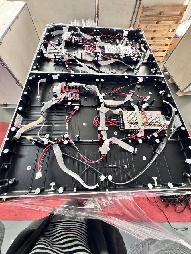
(1)Die cast aluminum cabinet, quick lock mechanism, alignment pins, rear leveling screws, magnetic base.
(2)Switching power supply, receiving card, soft HUB board, flexible signal ribbon cable, module DC power cable, Ethernet cable, cabinet parallel power supply cable, ground wire.
(3)Anti static strap, module suction tool, hex key, cable ties, insulating foam, spirit level.
二.Pre-assembly of the cabinet rear(Installing circuitry first, without the module):
(1)Fixed power supply, receiving card, soft HUB:
①Slot the power supply unit into the mounting bracket at the rear of the chassis and lightly secure it with screws.
②The receiving card is mounted next to the power supply, with the IN or OUT network ports facing outward.
③Mount the flexible HUB board near the front cable exit hole to minimize strain from long cable runs.
(2)Internal alignment of key initiatives:
①Plug the receiving card ribbon cable into the HUB input port, align the keyed notch and do not force it in.
②Connect the DC main output line to the HUB’s main power input terminals(red for positive, black for negative) and secure the connections firmly.
③Connect the cabinet grounding terminal to the yellow green ground wire, all aluminum housing must be grounded to prevent static electricity.
(3)Bring the thread out to the front side:
①Each output port on the hub is equipped with one flexible signal ribbon cable and one flexible DC power cable for the LED Display module , one set corresponds to a single module.
②Route all flexible cables through the exit points on the front of the enclosure, leaving 15 to 20mm of slack to prevent disconnection caused by pulling during screen adjustment, apply foam padding to the cable exit holes to prevent the cables from being cut.
③Neatly arrange the cables and avoid sharp, permanent creases, bending flexible ribbon cables at a 90 degree angle can easily cause internal breaks, leading to screen glitches.
三.Front service LED Module Assembly:
Put on your anti static wrist strap, remove the modules, and align the arrows to face the same direction, all pointing left or all pointing up:
(1)Single module connection sequence:
①Fully insert the flexible signal ribbon cable into the signal connector on the alignment module, ensuring alignment with the anti mis-insertion slot.
②Align the DC power cord with the module’s power port and snap it securely into place.
③One set of signal cables plus power cables corresponds to only one module, do not mix them up.
(2)Pick and place adsorption module:
①Align with the magnetic base on the unit and press down vertically to ensure a secure attachment.
②Fill the entire cabinet with modules, laying them out in sequence.
(3)Flatness inspection:
①No steps are felt at the horizontal or vertical seams between modules.
②For significant height differences, simply detach the module and make fine adjustments using the magnetic mount, there is ample slack in the flexible cable, so unplugging is unnecessary.
四.Full screen setup:
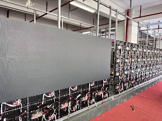
Assembly sequence: Start with the reference cabinet at the bottom left corner — install layer by layer, proceeding from left to right and bottom to top:
(1)Positioning and leveling of the first cabinet:
Hang or secure the cabinet body, but do not fully tighten the fasteners, use a level to check for horizontal and vertical alignment, and fine-tune the leveling screws at the four rear corners to ensure it is level.
(2)Joining of enclosure sections:
Ensure the alignment pins at the four corners of adjacent cabinets are fully inserted into the pin holes before locking the quick lock latches on all four sides, strictly avoid forcing the latches to lock, as this can compress the cabinets and cause permanent misalignment.
(3)Cross seam re inspection:
Pay special attention to leveling the intersection where the four cabinet units meet, if there is any height difference, release the locking mechanism, make fine adjustments using the set screws, and then re lock.
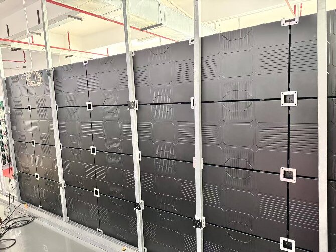
五.Signal and power supply cascading between enclosures:
(1)Signal or Network Cable Cascading:
①Connect the OUT port of the receiving card in the current cabinet to the IN port of the receiving card in the next cabinet in a daisy chain configuration leave the OUT port of the final cabinet unconnected.
②Prioritize using shielded network cables to reduce ripple interference.
(2)Parallel flexible power supply connection:
①Power supplies in adjacent enclosures are interconnected in parallel using DC flexible cables.
②Grouped by power rating, every 3 to 4 units are connected to an independent circuit breaker, the load is balanced across the three-phase power supply to prevent dimming caused by voltage drop at the end of the line.
③Leave some slack in the cabinet interconnection cables so that leveling, assembling, or disassembling the cabinets does not pull out the plugs.
六.Standard checks before powering on:
①All flexible ribbon cables and DC plugs are fully seated, there are no partially inserted connectors or bent pins.
②No aluminum frame extrusion, no sharp kinks, and no damage to the outer sheath.
③The power supply terminals are correctly connected (no polarity reversal) and free of short circuits, the enclosure is reliably grounded.
④Re tighten all locking mechanisms and wall mounting or suspension screws.
⑤Cables are sorted and bundled, high and low voltage lines are routed separately, without tangling or stacking.
七.Specific Precautions for Soft Connections:
①You must unplug the flexible cable before removing the module, do not pull the module directly by the ribbon cable, as this can easily cause the wires to break.
②The polarization slots on the ribbon cable must be aligned, inserting it the wrong way will burn out the module’s driver ICs.
③Ensure sufficient slack in the cable exit, if the cable is pulled too tight during fine adjustments of the cabinet, flickering or localized blackouts may occur.
④Post installation maintenance advantage, if a single module fails, it can be removed from the front via suction without dismantling the entire cabinet or affecting the wiring of adjacent cabinets.
 English
  简体中文
简体中文  Português do Brasil
  Italiano
  Español
  Français
  Deutsch
  한국어
한국어  日本語
日本語