
I. Preparazione pre-installazione Sicurezza + Precisione:
(1) Sopralluogo e conferma del progetto:
①Confermare la posizione di installazione (parete, colonna o sospensione), le dimensioni (lunghezza, altezza e profondità), la capacità di carico esterna ≥ 50 kg/m² e la tolleranza di planarità della parete ≤ 5 mm/m.
②Pianificare il percorso dei cavi di alimentazione e di segnale e riservare uno spazio di almeno 30 cm per la manutenzione sul retro.
③Determinare la disposizione dei moduli, nonché la quantità e la posizione degli alimentatori e delle schede riceventi.
(2) Elenco dei materiali e degli strumenti:
①Ridondanza, schede di ricezione, schede di invio, cavi di rete Cat 5e o Cat 6, cavi di alimentazione con anima in rame standard nazionale, struttura in acciaio o profili in alluminio, tasselli di espansione, fascette per cavi, canaline per cavi, connettori impermeabili.
②Materiali Moduli LED, Alimentatore switching 5V, Strumenti ≥20% Livella laser, Trapano elettrico, Trapano a percussione, Cacciavite, Braccialetto antistatico, Multimetro, Fascette per cavi, Metro a nastro.
(3) Pre-test del modulo Alimentazione di terra durante l'ispezione:
①Collegare il singolo modulo a un alimentatore da 5 V e a una scheda ricevente; all'accensione, verificare che non vi siano pixel morti, sfarfallii o distorsioni dello schermo e che i colori appaiano normali.
②Numerare secondo lo schema di layout per evitare errori nella sequenza di installazione.
II. Installazione di strutture in acciaio o telai in profilati di alluminio portanti + livellamento:
① Per la marcatura e il posizionamento delle linee, utilizzare una livella laser per tracciare linee di riferimento sulla superficie della parete; la deviazione orizzontale non deve superare i 2 mm.
②Montaggio a parete: Fissare le travi orizzontali e verticali alla parete utilizzando tasselli ad espansione; la distanza tra le travi orizzontali non deve superare i 60 cm, e tra le travi verticali gli 80 cm.
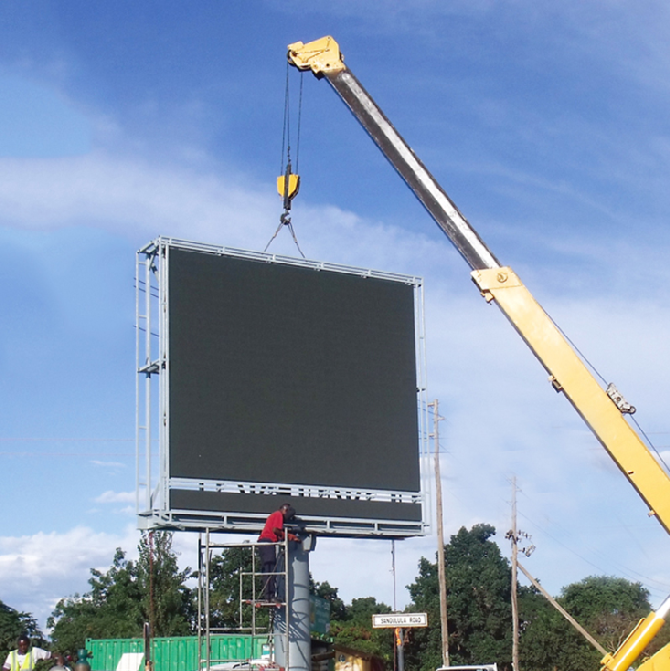
③Sollevamento: Per prima cosa, fissare i punti di sollevamento superiori, quindi fissare il telaio e regolare la planarità e l'allineamento verticale.
III. Cablaggio del segnale di alimentazione: instradare separatamente:
(1) Instradamento dei cavi di alimentazione: la sicurezza prima di tutto:
①Alimentazione zonale: l'alimentazione viene distribuita in base al numero di moduli di visualizzazione a LED; un alimentatore da 5 V/300 W supporta da 6 a 8 moduli P2 o P3.
②Cablaggio: Fase L → Rosso, Neutro N → Blu, Terra PE → Giallo o Verde, il collegamento di terra deve essere affidabile.
③Protezione dei condotti: i cavi di alimentazione devono essere instradati attraverso condotti o canaline in PVC, tenuti separati dai cavi di segnale per evitare interferenze.
④Uso all'aperto contenitore impermeabile Per i collegamenti, utilizzare un composto per incapsulamento per prevenire i cortocircuiti causati dall'acqua piovana.
(2) Il percorso del cavo di segnale garantisce che la direzione della cascata non venga invertita:
①Cavo di rete: Cat 5e o Cat 6, lunghezza ≤ 100 m, Scheda di invio → Scheda di ricezione (IN), Scheda di ricezione (OUT) → Scheda successiva (IN).
②Fissaggio: Il cavo di rete passa lungo il lato interno del telaio, fissato con fascette e chiaramente etichettato.
IV. Installazione dell'alimentatore e montaggio della scheda ricevente + cablaggio:
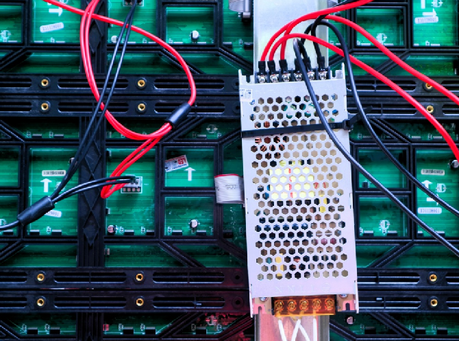
①Alimentatore fisso: l'alimentatore è montato sul retro del telaio, posizionato in modo da garantire ventilazione e dissipazione del calore, con uno spazio libero di ≥10 cm.
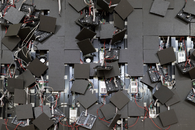
②La scheda ricevente è fissata alla trave del telaio, con la porta del cavo a nastro allineata verso i moduli.
③La scheda ricevente è preinstallata all'interno della Vetrina a LED, con i cavi a nastro già collegati in fabbrica.
④Ingresso 220 V, uscita 5 V. Collegare al modulo. È severamente vietato invertire la polarità.
⑤Collegare il cavo di rete agli ingressi IN e OUT e il cavo a nastro al modulo con la freccia rivolta verso l'ingresso IN.
5. Installazione dei moduli LED: Allineamento delle giunture e planarità:
①Indossa un braccialetto antistatico per evitare che le scariche elettrostatiche danneggino i LED.
②Dal basso verso l'alto, e dal centro verso l'esterno, iniziate con i blocchi di base, quindi espandetevi.
③Allinea i perni magnetici sul retro del modulo con la cornice, premi delicatamente per fissarlo tramite attrazione magnetica e livella il modulo.
④ Le viti M3 fissano i quattro angoli; utilizzare almeno 4 viti per pezzo, stringendole quanto basta per evitare di danneggiare la piastra frontale.
⑤Spazio tra i moduli ≤ 0,5 mm, differenza di altezza dei LED ≤ 0,5 mm, assenza di bordi neri o linee luminose.
⑥Dopo aver installato ogni fila, utilizzare una livella a bolla per verificare l'allineamento orizzontale e verticale ed effettuare immediatamente le regolazioni di precisione.
6. Ispezione obbligatoria prima dell'accensione - Per prevenire i cortocircuiti:
①I moduli, gli alimentatori e le schede riceventi sono fissati saldamente, senza viti allentate.
②I cavi di alimentazione e di segnale non contengono fili di rame esposti e i terminali positivo e negativo non sono collegati in modo inverso.
③ Messa a terra affidabile: il telaio, l'alimentatore e gli strati di schermatura del segnale condividono una massa comune.
VII. Accensione e messa in servizio del sistema Accensione + calibrazione:
①Innanzitutto, accendere l'interruttore generale e verificare che l'alimentazione a 220 V sia stabile, quindi, attivare singolarmente gli interruttori automatici per ciascuna zona, osservando che le spie di alimentazione funzionino normalmente.
②Accendi il computer e la scheda di invio, quindi collega la scheda di invio alla scheda di ricezione.
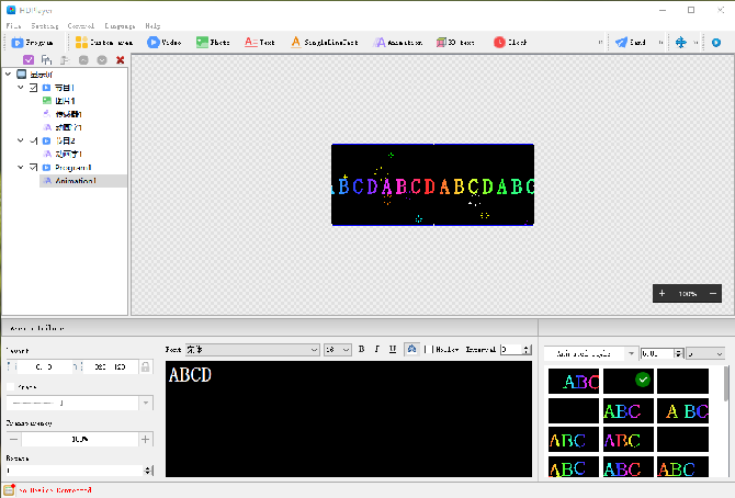
(1) Configurazione del software: prendendo come esempi NovaStar e Huidu:
① Installa il software di controllo e imposta la risoluzione dello schermo in larghezza e altezza in pixel.
②Configurare le schede riceventi: impostare la modalità di scansione, l'OE e la polarità dei dati, nonché la direzione di cascata in conformità con le specifiche del modulo.
③La configurazione del layout dello schermo consente di impostare la disposizione dei moduli e la distribuzione del carico della scheda ricevente.
④Calibrazione punto per punto della luminosità e del colore, eliminando discrepanze cromatiche e linee chiare e scure.
⑤Test: Visualizza a schermo intero i colori bianco, rosso, verde e blu, verifica la presenza di pixel morti, disallineamenti e sfarfallii.
VIII. Finalizzazione e accettazione garantite + protezione:
① Tutti i cavi sono ordinatamente raggruppati con fascette, posizionati all'interno delle canaline portacavi e chiaramente etichettati.
②Attorno al perimetro del pannello del display viene applicato un sigillante impermeabile e tutte le interfacce vengono sigillate per impedire l'infiltrazione dell'acqua piovana.
③ Sul retro sono presenti delle aperture di ventilazione, per le quali è possibile installare una ventola in ambienti ad alta temperatura.
④Dopo 24 ore di funzionamento continuo, non si sono verificati arresti anomali del sistema, distorsioni dello schermo o pixel morti; il display ha funzionato normalmente.
 Italiano
  English
  简体中文
简体中文  Português do Brasil
  Español
  Français
  Deutsch
  한국어
한국어  日本語
日本語